Bulldog Security INSTALLATION GUIDE Installation Manual
Browse online or download Installation Manual for Car alarm Bulldog Security INSTALLATION GUIDE. Bulldog Security INSTALLATION GUIDE Installation manual User Manual
- Page / 8
- Table of contents
- BOOKMARKS
Summary of Contents
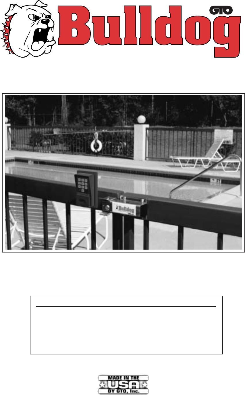
8, Inc.PEDESTRIAN GATE LOCKInstallation ManualPLEASE NOTE ... due to the variety of possible mounting applications, no mount-ing hardware for the lock
1Before You Start ...The installation has two parts ...• Mounting The Lock and Control Box• Wiring The Control BoardOnce you have the necessary wire a
2, Inc.AUTOMATIC SOLENOIDSECURITY GATE LOCKParts IdentificationA - Lock w/ 20' of Low Voltage WireB - Lock ReceiverC - Clevis PinD - Locking CapE
3Mounting The Lock:Step 1: With the gate in the closed position determine the best location for the lock and receiver.Attach the lock to a solid surfa
4Clevis PinReceiverLocking CapBulldog LockUbolts, saddles & nuts (not provided)Remember to check the alignment and mark positions before drilling
54321Battery TerminalsTerminal BlockControl Box AssemblyPress the strain relief into thecontrol box until it clickssecurely in place.Press the control
6Wiring the Control BoardStep 1: Attach the RED (+) battery lead wire to control board terminal #5 and the BLACK (–) battery wire tocontrol board term
7If you have questions please call our technical service number:1-800-543-1236Available Accessories:GTO DIGITAL KEYPAD ... The weatherproof digital ke
Related products and manuals for Car alarm Bulldog Security INSTALLATION GUIDE
 (14 pages)
© 2020, manymanuals.com. All rights reserved. | 1.447 s |
 Manymanuals.com
 Manymanuals.de
 Manymanuals.fr
 Manymanuals.it
 Manymanuals.pl
 Manymanuals.cz
 Manymanuals.es
 Manymanuals-pt.com
Comments to this Manuals